
It has been assumed as an example that the tooth profiles 6 of gear 1 are circular arcs of radii 7 and centers 8, in the shown normal section.

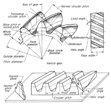
Fig. 2.7D illustrates the said normal section 2-2 for both pinion 4 and gear 1. It is customary to analyze helical gearing with reference to a normal section, that is, line 2-2 of Fig. 2.7A, line 2-2 being normal to the helix of the pitch circle. In order to clearly illustrate the degree of contact between the teeth of the gear and pinion the tooth 4 is shown in section in Fig. 2.7A. Referring to the drawings, and particularly to Fig. 2.7A and D, 1 denotes a helical gear having teeth 2 in contact with the teeth 3 of a mating pinion 4. The helical gearing is illustratively exemplified in the accompanying drawings, in which Fig. 2.7A is a side elevational view of the proposed gear showing parts thereof in section Fig. 2.7D is a normal sectional view if Fig. 2.7A, taken on the lines 2-2 of the latter figure Fig. 2.7G is a side elevational view of a pair of gears constructed in accordance with the invention Fig. 2.7H is a sectional view taken through a pair of gears Fig. 2.7B and C are sectional views of milling cutters used in the manufacture of gear of the proposed design Fig. 2.7E and F are elevational views of corresponding tools of rack shape, to be used in reciprocating machines for cutting helical gears in accordance with the invention Fig. 2.7K and L are side elevational views of the improved gear showing a pair of grinding wheels in different operating positions, the wheels being set to grind opposite tooth surfaces Fig. 2.7M is a view of a gear taken in normal section and showing the grinding wheels in operation position Fig. 2.7N is a view of a mate pinion showing the grinding wheels in operating position Fig. 2.7O is a view of modified form of gear made in accordance with the invention Fig. 2.7J is a sectional view taken through an internal gear and its pinion Fig. 2.7Q is a normal section through helical teeth of composite outline, constructed from the invention Fig. 2.7P is a view of reciprocating tool of rack shape in operating position and Fig. 2.7S is a view of a modified type of reciprocating tools, in position to start a cut on a herringbone gear.įigure 2.7.


 0 kommentar(er)
